Safety procedure and proper handling of tool is highly observed when working any electronic components to avoid risk of unnecessary further damages whatever you are working at. These are the following thing that always to remind when working any electronic components such as cellphones.
Antistatic Wrist Strap
Wear a Ground Strap.
Anti static wrist strap is used to avoid risk of electrostatic discharge from a human body to an electronic component circuit.
An antistatic wrist strap, ESD wrist strap, or ground bracelet is an antistatic device used to prevent electrostatic discharge (ESD) by safely grounding a person working on electronic equipment.

It consists of a stretchy band of fabric with fine conductive fibers woven into it. The fibers are usually made of carbon or carbon-filled rubber, and the strap is bound with a stainless steel clasp or plate. They are usually used in conjunction with an antistatic mat on the workbench, or a special static-dissipating plastic laminate on the workbench surface.
Hand Gloves
You are not just protecting your hand from posibble burns or brushes. it also protect the cellphones from scratches and possible electrostatic discharge. A cotton cloth made glove is essential to use.

Safety Handling with Rework and Soldering Stations
Rework and soldering Station is a hot surface devices and can cause fire instanly and extreme burns on skin when unproperly handled.
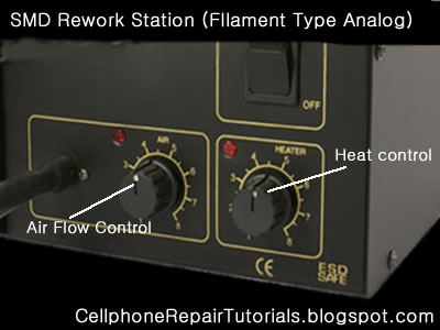
Always Observe and Set it in proper heat and air flow amounts.
Secure a safe place on your table where the rework station is located. Avoid inplacing it that people may pass or standing by especially kids.
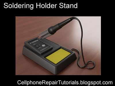
Always shut it off when not in use and place unto the holder stand to avoid risk of fire and skin burns.
Safety Handling of a Multitester
a multitester may damaged easily when unproperly handled. always check ranges when checking voltages and currents. The deplection yoke of the analog meter may be bust out when overdrive by a current to it.
Measuring Resistance
Set the multimeter to Ohms or Resistance (turn meter on if it has a separate power switch). Understand that resistance and continuity are opposites. The multimeter measures resistance in ohms, it can not measure continuity. When there is little resistance there is a great deal of continuity. Conversely, when there is a great deal of resistance, there is little continuity. With this in mind, when we measure resistance we can make assumptions about continuity based on the resistance values measured. Observe the meter indication. If the test leads are not in contact with anything, the needle or pointer of an analog meter will be resting at the left most position. This is represents an infinite amount of resistance, or an "open circuit"; it is also safe to say there is the no continuity, or path between the black and red probes. Careful inspection of the dial should reveal the OHM scale. It is usually the top-most scale and has values that are highest on the left of the dial (a sideways "8" for infinity) and gradually reduce to 0 on the right. This is opposite of the other scales; they have the lowest values on the left and increase going right.
Mesuring Voltage Ac-DC
Set the meter for the highest range provided for AC or DC Volts. Many times, the voltage to be measured has a value that is unknown. For this reason, the highest range possible is selected so that the meter circuitry and movement will not be damaged by voltage greater than expected.
Measuring Current by Ampere
Set the meter to the highest AC or DC Amp range supported. If the circuit to be tested is AC but the meter will only measure DC amps (or vice-versa), stop. The meter must be able to measure the same mode (AC or DC) Amps as the voltage in the circuit, otherwise it will indicate 0.
Be aware that most multimeters will only measure extremely small amounts of current, in the uA and mA ranges. 1 uA is .000001 amp and 1 mA is .001 amp. These are values of current that flow only in the most delicate electronic circuits, and are literally thousands (and even millions) of times smaller than values seen in the home and automotive circuits that most homeowners would be interested testing. Just for reference, a typical 100W / 120V light bulb will draw .833 Amps. This amount of current would likely damage the meter beyond repair. A "clamp-on" type ammeter would be ideal for the typical homeowner requirements, and does not require opening the circuit to take measurements (see below). If this meter were to be used to measure current through a 4700 ohm resistor across 9 Volts DC, it would be done as outlined below:
Safety Handling of a Power Supply
Power supply may also damaged and cause damaged to a component..
Always set it and determine the correct amount of Voltage range to avoid risk of blowing out any electronic parts.
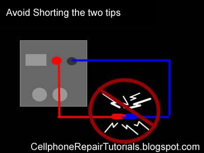
Do not short the two alligator clips because the power supply will heat up and may busted out the protection fuse.
Using a multimeter is quite bit difficult for the first time especially the analog type one unlike the digital which is more convenient to use for beginners.
Every multimeter have its own user manual accompanied when you purchased it at any electronics store in your areas, and each one varies on how each circuits designed but there's always only one thing in common,
a Multimeter is is used to measure voltages AC or DC, currents and resistance, continuity and electronics components.
Maybe this only a take brief explanation on how to use a multimeter,
I have an example copy around here using my Sanwa analog multimeter which is made from Japan.
PARTS OF A MULTIMETER
1.) Indicator Zero Connector 7.) Measuring Terminal +
2.) Indicatot Pointer 8.) Measurin Terminal - COM
3.) Indicator Scale 9.) Series Terminal Capacitor OUTPUT
4.) Continuity Indicating 10.) Panel
LED ( CONTINUITY ) 11.) Rear Case
5.) Range Selector Switch knob
6.) 0-ohms adjusting knob
/0- centering meter
(NULL meter) adjusting knob
EXPLANATION ABOUT THE SCALE
1.) Resistance (OHMS) scale
2.) DCV, A scale and ACV scale
(10V or more)
3.) 0-centerig (NULL) +/- DCV scale
4.) ACV 2.5 (AC 2.5V) exclusive scale
5.) Transistor DC amplification factor
(hFE) scale
6.) 1.5 baterry test (BATT 1.5V)
7.) OHMS range terminal to terminal current
(Li) scale)
8.) OHMS range terminal to terminal voltage
(LV) scale
9.) Decibel (dB) scale
10.) Continuity Indicating LED
11.0 Mirror: To obtain most accurate readings,
the mirror is deviced to make operator eyes, the indicator pointer, and the indicator pointer reflexed to the mirror put together in line.
How to Measure Resistance
Multimeter with selector set to "Ohms". This meter only has a single Ohms range.Multimeter with selector set to "Ohms". This meter only has a single Ohms range.
Set the multimeter to Ohms or Resistance (turn meter on if it has a separate power switch). Understand that resistance and continuity are opposites. The multimeter measures resistance in ohms, it can not measure continuity. When there is little resistance there is a great deal of continuity. Conversely, when there is a great deal of resistance, there is little continuity. With this in mind, when we measure resistance we can make assumptions about continuity based on the resistance values measured. Observe the meter indication. If the test leads are not in contact with anything, the needle or pointer of an analog meter will be resting at the left most position. This is represents an infinite amount of resistance, or an "open circuit"; it is also safe to say there is the no continuity, or path between the black and red probes. Careful inspection of the dial should reveal the OHM scale. It is usually the top-most scale and has values that are highest on the left of the dial (a sideways "8" for infinity) and gradually reduce to 0 on the right. This is opposite of the other scales; they have the lowest values on the left and increase going right.
Connect the black test lead to the jack marked "Common" or "-"
Connect the red test lead to the jack marked with the Omega (Ohm symbol) or letter "R" near it.
Set the range (if provided) to R x 100.
Hold the probes at the end of the test leads together. The meter pointer should move fully to the right. Locate the "Zero Adjust" knob and rotate so that the the meter indicates "0" (or as close to "0" as possible). Note that this position is the "short circuit" or "zero ohms" indication for this R x 1 range of this meter. Always remember to "zero" the meter immediately after changing resistance ranges.
Replace batteries if needed. If unable to obtain a zero ohm indication, this may mean the batteries are weak and should be replaced. Retry the zeroing step above again with fresh batteries.
Measure resistance of something like a known-good lightbulb. Locate the two electrical contact points of the bulb. They will be the threaded base and the center of the bottom of the base. Have a helper hold the bulb by the glass only. Press the black probe against the threaded base and the red probe against the center tab on the bottom of the base. Watch the needle move from resting at the left and move quickly to 0 on the right.
Change the range of the meter to R x 1. Zero the meter again for this range. Repeat the step above. Observe how the meter did not go as far to the right as before. The scale of resistance has been changed so that each number on the R scale can be read directly. In the previous step, each number represented a value that was 100 times greater. Thus, 150 really was 15,000 before. Now, 150 is just 150. Had the R x 10 scale been selected, 150 would have been 1,500. The scale selected is very important for accurate measurements. With this understanding, study the R scale. It is not linear like the other scales. Values at the left side are harder to accurately read than those on the right. Trying to read 5 ohms on the meter while in the R x 100 range would look like 0. It would be much easier at the R x 1 scale instead. This is why when testing resistance, adjust the range so that the readings may be taken from the middle rather than the extreme left or right sides.
Test resistance between hands. Set the meter to the highest R x value possible. Zero the meter. Loosely hold a probe in each hand and read the meter. Squeeze both probes tightly. Notice the resistance is reduced. Let go of the probes and wet your hands. Hold the probes again. Notice that the resistance is lower still. For these reasons, it is very important that the probes not touch anything other than the device under test. A device that has burned out will not show "open" on the meter when testing if your fingers provide an alternate path around the device, like when they are touching the probes. Testing round cartridge type and older style glass automotive fuses will indicate low values of resistance if the fuse is lying on a metal surface when under test. The meter indicates the resistance of the metal surface that the fuse is resting upon (providing an alternate path between the red and black probe around the fuse) instead of trying to determine resistance through the fuse. Every fuse, good or bad, will indicate "good".
How to Measure Voltage
Set the meter for the highest range provided for AC Volts. Many times, the voltage to be measured has a value that is unknown. For this reason, the highest range possible is selected so that the meter circuitry and movement will not be damaged by voltage greater than expected. If the meter were set to the 50 volt range and a common U.S. electrical outlet were to be tested, the 120 volts present could irreparably damage the meter. Start high, and work downward to the lowest range that can be safely displayed.
Insert the black probe in the "COM" or "-" jack.
Insert the red probe in the "V" or "+" jack.
Locate the Voltage scales. There may be several Volt scales with different maximum values. The range chosen the selector knob determines which voltage scale to read. The maximum value scale should coincide with selector knob ranges. The voltage scales, unlike the Ohm scales, are linear. The scale is accurate anywhere along its length. It will of course be much easier accurately reading 24 volts on a 50 volt scale than on a 250 volt scale, where it might look like it is anywhere between 20 and 30 volts.
Test a common electrical outlet. In the U.S. you might expect 120 volts or even 240 volts. In other places, 240 or 380 volts might be expected. Press the black probe into one of the straight slots. It should be possible to let go of the black probe, as the contacts behind the face of the outlet should grip the probe, much like it does when a plug is inserted. Insert the red probe into the other straight slot. The meter should indicate a voltage very close to 120 or 240 volts (depending on type outlet tested). Remove the probes, and rotate the selector knob to the lowest range offered, that is greater than the voltage indicated (120 or 240). Reinsert the probes again as described earlier. The meter may indicate between 110 and as much as 125 volts this time. The range of the meter is important to obtain accurate measurements. If the pointer did not move, it is likely that DC was chosen instead of AC. The AC and DC modes are not compatible. The correct mode MUST be set. If not set correctly, the user would mistakenly believe there was no voltage present. This could be deadly. Be sure to try BOTH modes if the pointer does not move. Set meter to AC volts mode, and try again. Whenever possible, try to connect at least one probe in such a way that it will not be required to hold both while making tests. Some meters have accessories that include alligator clips or other types of clamps that will assist doing this. Minimizing your contact with electrical circuits drastically reduces that chances of sustaining burns or injury.
How to Measure Current Amperes
Determine if AC or DC by measuring the voltage of the circuit as outlined above.
Set the meter to the highest AC or DC Amp range supported. If the circuit to be tested is AC but the meter will only measure DC amps (or vice-versa), stop. The meter must be able to measure the same mode (AC or DC) Amps as the voltage in the circuit, otherwise it will indicate 0.
Be aware that most multimeters will only measure extremely small amounts of current, in the uA and mA ranges. 1 uA is .000001 amp and 1 mA is .001 amp. These are values of current that flow only in the most delicate electronic circuits, and are literally thousands (and even millions) of times smaller than values seen in the home and automotive circuits that most homeowners would be interested testing. Just for reference, a typical 100W / 120V light bulb will draw .833 Amps. This amount of current would likely damage the meter beyond repair. A "clamp-on" type ammeter would be ideal for the typical homeowner requirements, and does not require opening the circuit to take measurements (see below). If this meter were to be used to measure current through a 4700 ohm resistor across 9 Volts DC, it would be done as outlined below:
Insert the black probe into the "COM" or "-" jack.
Insert the red probe into the "A" jack.
Shut off power to the circuit.
Open the portion of the circuit that is to be tested (one lead or the other of the resistor). Insert the meter in series with the circuit such that it completes the circuit. An ammeter is placed IN SERIES with the circuit to measure current. It cannot be placed "across" the circuit the way a voltmeter is used (otherwise the meter will probably be damaged). Polarity must be observed. Current flows from the positive side to the negative side. Set the range of current to the highest value.
Apply power and adjust range of meter downward to allow accurate reading of pointer on the dial. Do not exceed the range of the meter, otherwise it may be damaged. A reading of about 2 milliamps should be indicated since from Ohm's law I = V / R = (9 volts)/(4700 Ω) = .00191 amps = 1.91 mA.
If you're measuring the current consumed by the device itself, be aware of any filter capacitors or any element that requires an inrush (surge) current when switched on. Even if the operating current is low and within the range of the meter fuse, the surge can be MANY times higher than the operating current (as the empty filter capacitors are almost like a short circuit). Blowing the meter fuse is almost certain if the DUT's (device under test) inrush current is many times higher than the fuses rating. In any case, always use the higher range measurement protected by the higher fuse rating (if your meter has two fuses), or just be careful.
How to Check Basic Electronic Components Using a Multi-Meter
Basic electronic components such as resistors, capacitors, diodes and transistors are widely used in any electronic devices and gadgets. Knowing how to conduct a test on this components using a multimeter would give you an idea on how to trouble shoot and repair any defective cellphones or electronic equipments at home. Below are some basic D.I.Y. regarding proper testing of this components using a multimeter.
How to Check Resistors?
Read the indicated code value indicated in Schematic Diagram then select the Ohm-scale within but not way below the indicated value. A resistor is good if its resistance is close to the indicated value.Tolerance should be considered with the ohmmeter reading. While, no resistance reading at all on the ohmmeter scale settings means that the resistor is open. A zero resistance reading on all ohmmeter scale settings means that the resistor is shorted.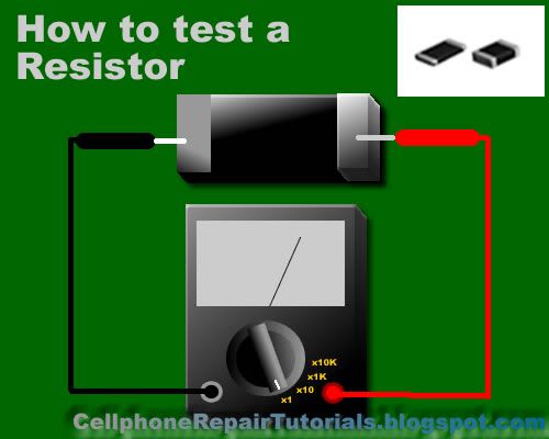
How to Check Capacitors?
In most cases, a capacitor fails due to the deterioration of the dielectric material between its plate.Defective capacitors can have an internal shorted terminals, excessive leakage and degradation of capacitance meter. For an electrolytic capacitor (capacitors with polarity), short the terminal capacitor to discharge it prior to testing.
To test a capacitor, set the multimeter to Rx10 or Rx1K scale. Connect the tester negative probe to the capacitor positive terminal and the positive probe to the negative terminal.
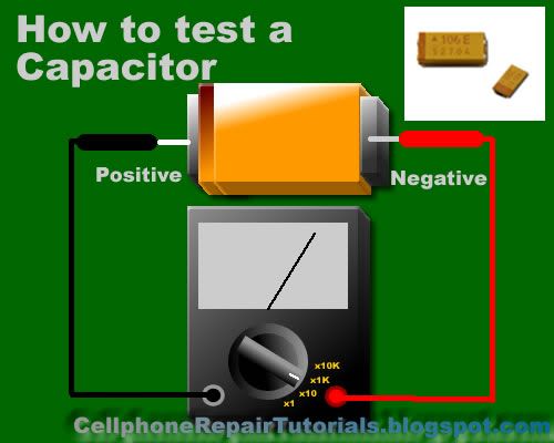
A good indication for electrolytic capacitor shows the meter needle deflecting towards zero and moves back again to infinite resistance position.
For ceramic, Mylar and other capacitor with a capacitance with less than 1.0 uF, the meter will not deflect at all.
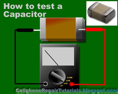
A defective indication for an electrolytic capacitor shows that the meter will rest on zero and remain stationary at a point which is an indication that the capacitor is shorted.
How to Check Diodes?
Set the multimeter knob to any of the resistance position (x1, x10, x1K or 10K ohm ).Connect the positive probe to the anode and the negative probe to the cathode.Then connect the positive probe to the cathode and the
negative probe to the anode of the diode. A good indication in the first procedure will show the meter deflected very little or may not deflect at all.
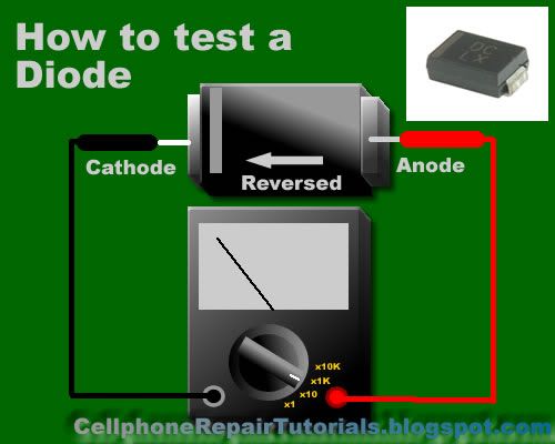
And in the second procedure, the meter will deflect towards zero.The actual resistance reading is the forward resistance of the diode.
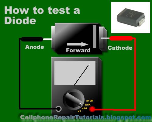
A defective indication shows that the meter won't deflect at all even when the probes are reversed. Or the meter deflects at the same time or almost the same resistance reading for both steps.
How to Check Transistors:
Bipolar transistors are usually checked out of a circuit by means of an ohmmeter. When it is desired to check for the resistance across the transistor emitter and collector, NPN or PNP, ohmmeter probes may be connected either way. A good transistor will show above a reading above 1000 ohm.
How to determine if it is NPN or PNP transistor?
To determine the correct terminal of the transistors, set the range selector to x 1 or 10 ohm.Connect the positive probe to the emitter and the negative probe to the base of the transistor. Note the reading interchange the connection of the probes to the leads of the transistor.
Base your conclusion on the table:
POSITIVE PROBE TO: -----NEGATIVE PROBE TO: -----RESISTANCE READING-- CONCLUSION:
Emitter------- -- Base---------- Less than 150 ohm ------Transistor is NPN
Base --------------Emitter --------Infinity ----------------Transistor is NPN
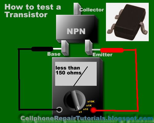
POSITIVE PROBE TO: NEGATIVE PROBE TO: RESISTANCE READING: CONCLUSION:
-Emitter------------Base ---------Infinity ---------------- Transistor is PNP
Base --------------- Emitter --- - Less than 150 ohm ------- Transistor is PNP
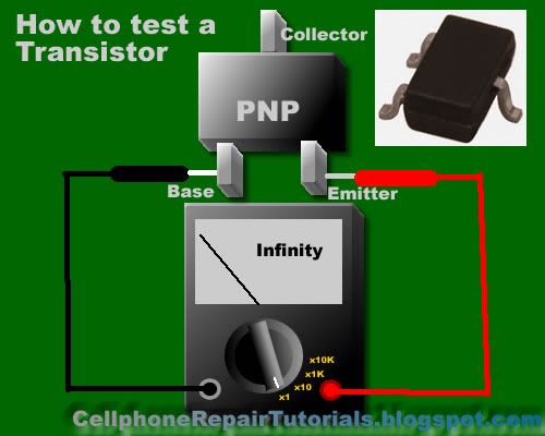
Some defective indications of transistors: Resistance between any pair of the terminals is less than 10 ohms, means that the transistor is shorted. Resistance between base and emitter or base collector for both the forward and reverse application of ohmmeter probes is infinity (meter needle don't deflect), means that the transistor is open. Transistors overheats (except power transistors) during normal operating condition means that the transistor is shorted.
How to Check an LED ( Light Emitting Diode)
Set the Muti-meter to x1 connect the positive probe to cathode and the negative probe to anode. The good and working LED will then light up or glow, a busted LED will not.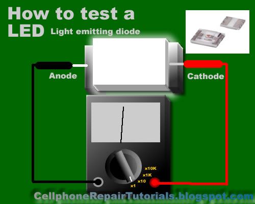
How to Check a Coil?
Set the multimeter to X1 a good and working coil have a reading approximately point to zero ohms, without any reading means the coil is open or busted.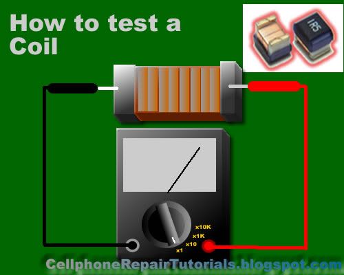
How to Check a Fuse?
A blown SMD Fuse is not visible to our naked eye, just set the multi-meter to x1 and put both test probe to both end side of the fuse. A full reading here to zero or continuity check is full. without any reading means the fuse is already busted.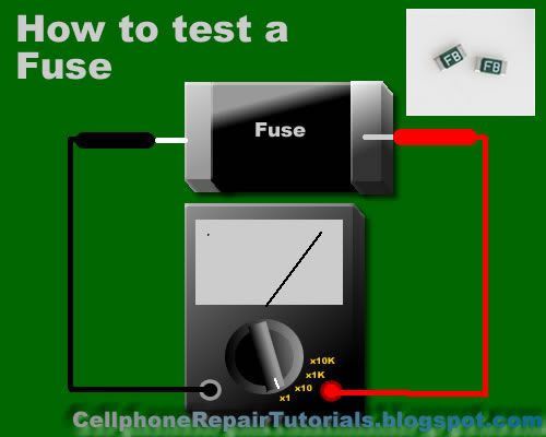
How to Check IC chips (Integrated Circuits)?
IC Chips is hard to determine faulty by using only a multi-meter, some advance equipment like the one that the manufacturer used during their productions. However; you can determine a faulty chips by some few experiences when it comes to troubleshooting, One techniques is that by comparing two same components from one another. like for example; if one chips is suspected to be faulty, then by replacing it with a good and working same chips, you can now determine it if the said chips got a problem. It is a trial and error method at first; but as long as your experience and knowledge skills increases, you can determine it more quickly and accurately.Further, we will tackle this issues and give you some tips and tricks.




may know pls ,functions of parts
ReplyDelete