Definition of Electronics:
Electronics is the branch of science that deals with the study of flow and control of electrons (electricity) and the study of their behavior and effects in vacuums, gases, and semiconductors, and with devices using such electrons. This control of electrons is accomplished by devices that resist, carry, select, steer, switch, store, manipulate, and exploit the electron.
Electronics isn't always easy, but you can learn. And you can do it without memorizing theories and formulas belong in a Physics text. the focus of this program is learning how things work. Electronics may defined as an art of knowledge to make such impossible things work. Things such as Televisions, AM/FM Radios, Computers and ob course the mobile phones and etc. We are surrounded by electronics....What is Ohm's Law?
Ohm's Law is made from 3 mathematical equations that shows the relationship between electric voltage, current and resistance.
What is voltage? An anology would be a huge water tank filled with thousands of gallons of water high on a hill.
The difference between the pressure of water in the tank and the water that comes out of a pipe connected at the bottom leading to a faucet is determined by the size of the pipe and the size of the outlet of the faucet. This difference of pressure between the two can be thought of as potential Voltage.
What is current? An analogy would be the amount of flow determined by the pressure (voltage) of the water thru the pipes leading to a faucet. The term current refers to the quantity, volume or intensity of electrical flow, as opposed to voltage, which refers to the force or "pressure" causing the current flow.
What is resistance? An analogy would be the size of the water pipes and the size of the faucet. The larger the pipe and the faucet (less resistance), the more water that comes out! The smaller the pipe and faucet, (more resistance), the less water that comes out! This can be thought of as resistance to the flow of the water current.
All three of these: voltage, current and resistance directly interact in Ohm's law.
Change any two of them and you effect the third.
Info: Ohm's Law was named after Bavarian mathematician and physicist Georg Ohm.
Ohm's Law can be stated as mathematical equations, all derived from the
same principle.
In the following equations,
V is voltage measured in volts (the size of the water tank),
I is current measured in amperes (related to the pressure (Voltage) of water thru the pipes and faucet) and
R is resistance measured in ohms as related to the size of the pipes and faucet:
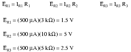
V = I x R (Voltage = Current multiplied by Resistance)
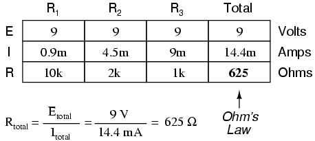
R = V / I (Resistance = Voltage divided by Current)
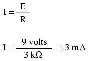
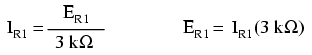
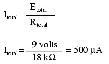
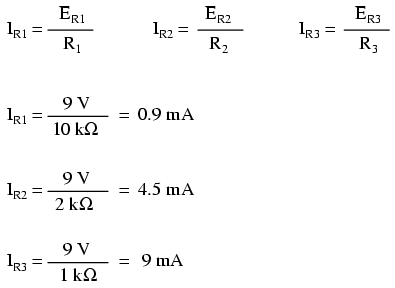
I = V / R (Current = Voltage Divided by Resistance)
Knowing any two of the values of a circuit, one can determine (calculate) the third, using Ohm's Law.
For example, to find the Voltage in a circuit:
If the circuit has a current of 2 amperes, and a resistance of 1 ohm, (< these are the two "knowns"), then according to Ohms Law and the formulas above, voltage equals current multiplied by resistance:
(V = 2 amperes x 1 ohm = 2 volts).
To find the current in the same circuit above assuming we did not know it but we know the voltage and resistance:
I = 2 volts divided by the resistance 1 ohm = 2 amperes.
In this third example we know the current (2 amperes) and the voltage (2 volts)....what is the resistance?
Substituting the formula:
R = Volts divided by the current (2 volts divided by 2 amperes = 1 ohm
Sometimes it's very helpful to associate these formulas Visually. The Ohms Law "wheels" and graphics below can be a very useful tool to jog your memory and help you to understand their relationship.

The wheel above is divided into three sections:
Volts V (on top of the dividing line)
Amps (amperes) I (lower left below the dividing line)
Resistance R (lower right below the dividing line)
X represents the (multiply by sign)
Memorize this wheel
To use, just cover the unknown quantity you need with your minds eye and what is left is the formula to find the unknown.
Example:
To find the current of a circuit (I), just cover the I or Amps section in your mines eye and what remains is the V volts above the dividing line and the R ohms (resistance) below it. Now substitute the known values. Just divided the known volts by the known resistance.
Your answer will be the current in the circuit.
The same procedure is used to find the volts or resistance of a circuit!
Here is another example:
You know the current and the resistance in a circuit but you want to find out the voltage.
Just cover the voltage section with your minds eye...what's left is the I X R sections. Just multiply the I value times the R value to get your answer! Practice with the wheel and you'll be surprised at how well it works to help you remember the formulas without trying!
 This Ohm's Law Triangle graphic is also helpful to learn the formulas.
Just cover the unknown value and follow the graphic as in the yellow wheel examples above.
You'll have to insert the X between the I and R in the graphic and imagine the horizontal divide line but the principal is just the same.

In the above Ohm's law wheel you'll notice that is has an added section (P) for Power and the letter E* has been used instead of the letter V for voltage.
This wheel is used in the exact same fashion as the other wheels and graphics above.
You will also notice in the blue/green areas there are only two known values with the unknown value in the yellow sections. The red bars separate the four units of interest.
An example of the use of this wheel is:
Let's say that you know the power and the current in a circuit and want to know the voltage.
Find your unknown value in the yellow areas (V or E* in this wheel) and just look outward and pick the values that you do know. These would be the P and the I. Substitute your values in the formula, (P divided by I) do the math and you have your answer!
Info: Typically, Ohm's Law is only applied to DC circuits and not AC circuits.
* The letter "E" is sometimes used in representations of Ohm's Law for voltage instead of the "V" as in the wheel above.
Learning how things work can be fun.
With this skill you can Build things.
make better use of things
and repair things..
have better job opportunities
An important part of learning electronics
is the the need to visualize the action inside a piece of equipment. In electronics things happen at a sub-atomic level. to understand what is happening, you need a mental picture, a visualization of events you can see directly. You need a in your mind of how events are turned on and off. you need to visualize signals being amplified and attenuated. ( These are long words for being made bigger and smaller )
take an overview of electronic equipment. Inside anything what's happening can be describe as some kind of source delivering power to some kind of a load. The terms source and load become clearer as you can discover a few basics. A source is where the energy comes from. A load is what does the work. When power is delivered to a load, the load produces sound, heat, pictures or anything else that can be produced electronically..
Electronics is the branch of science that deals with the study of flow and control of electrons (electricity) and the study of their behavior and effects in vacuums, gases, and semiconductors, and with devices using such electrons. This control of electrons is accomplished by devices that resist, carry, select, steer, switch, store, manipulate, and exploit the electron.
Electronics isn't always easy, but you can learn. And you can do it without memorizing theories and formulas belong in a Physics text. the focus of this program is learning how things work. Electronics may defined as an art of knowledge to make such impossible things work. Things such as Televisions, AM/FM Radios, Computers and ob course the mobile phones and etc. We are surrounded by electronics....What is Ohm's Law?
Ohm's Law is made from 3 mathematical equations that shows the relationship between electric voltage, current and resistance.
What is voltage? An anology would be a huge water tank filled with thousands of gallons of water high on a hill.
The difference between the pressure of water in the tank and the water that comes out of a pipe connected at the bottom leading to a faucet is determined by the size of the pipe and the size of the outlet of the faucet. This difference of pressure between the two can be thought of as potential Voltage.
What is current? An analogy would be the amount of flow determined by the pressure (voltage) of the water thru the pipes leading to a faucet. The term current refers to the quantity, volume or intensity of electrical flow, as opposed to voltage, which refers to the force or "pressure" causing the current flow.
What is resistance? An analogy would be the size of the water pipes and the size of the faucet. The larger the pipe and the faucet (less resistance), the more water that comes out! The smaller the pipe and faucet, (more resistance), the less water that comes out! This can be thought of as resistance to the flow of the water current.
All three of these: voltage, current and resistance directly interact in Ohm's law.
Change any two of them and you effect the third.
Info: Ohm's Law was named after Bavarian mathematician and physicist Georg Ohm.
Ohm's Law can be stated as mathematical equations, all derived from the
same principle.
In the following equations,
V is voltage measured in volts (the size of the water tank),
I is current measured in amperes (related to the pressure (Voltage) of water thru the pipes and faucet) and
R is resistance measured in ohms as related to the size of the pipes and faucet:
V = I x R (Voltage = Current multiplied by Resistance)
R = V / I (Resistance = Voltage divided by Current)
I = V / R (Current = Voltage Divided by Resistance)
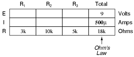
Knowing any two of the values of a circuit, one can determine (calculate) the third, using Ohm's Law.
For example, to find the Voltage in a circuit:
If the circuit has a current of 2 amperes, and a resistance of 1 ohm, (< these are the two "knowns"), then according to Ohms Law and the formulas above, voltage equals current multiplied by resistance:
(V = 2 amperes x 1 ohm = 2 volts).
To find the current in the same circuit above assuming we did not know it but we know the voltage and resistance:
I = 2 volts divided by the resistance 1 ohm = 2 amperes.
In this third example we know the current (2 amperes) and the voltage (2 volts)....what is the resistance?
Substituting the formula:
R = Volts divided by the current (2 volts divided by 2 amperes = 1 ohm
Sometimes it's very helpful to associate these formulas Visually. The Ohms Law "wheels" and graphics below can be a very useful tool to jog your memory and help you to understand their relationship.
The wheel above is divided into three sections:
Volts V (on top of the dividing line)
Amps (amperes) I (lower left below the dividing line)
Resistance R (lower right below the dividing line)
X represents the (multiply by sign)
Memorize this wheel
To use, just cover the unknown quantity you need with your minds eye and what is left is the formula to find the unknown.
Example:
To find the current of a circuit (I), just cover the I or Amps section in your mines eye and what remains is the V volts above the dividing line and the R ohms (resistance) below it. Now substitute the known values. Just divided the known volts by the known resistance.
Your answer will be the current in the circuit.
The same procedure is used to find the volts or resistance of a circuit!
Here is another example:
You know the current and the resistance in a circuit but you want to find out the voltage.
Just cover the voltage section with your minds eye...what's left is the I X R sections. Just multiply the I value times the R value to get your answer! Practice with the wheel and you'll be surprised at how well it works to help you remember the formulas without trying!
This Ohm's Law Triangle graphic is also helpful to learn the formulas.Just cover the unknown value and follow the graphic as in the yellow wheel examples above.
You'll have to insert the X between the I and R in the graphic and imagine the horizontal divide line but the principal is just the same.
In the above Ohm's law wheel you'll notice that is has an added section (P) for Power and the letter E* has been used instead of the letter V for voltage.
This wheel is used in the exact same fashion as the other wheels and graphics above.
You will also notice in the blue/green areas there are only two known values with the unknown value in the yellow sections. The red bars separate the four units of interest.
An example of the use of this wheel is:
Let's say that you know the power and the current in a circuit and want to know the voltage.
Find your unknown value in the yellow areas (V or E* in this wheel) and just look outward and pick the values that you do know. These would be the P and the I. Substitute your values in the formula, (P divided by I) do the math and you have your answer!
Info: Typically, Ohm's Law is only applied to DC circuits and not AC circuits.
* The letter "E" is sometimes used in representations of Ohm's Law for voltage instead of the "V" as in the wheel above.
Learning how things work can be fun.
With this skill you can Build things.
make better use of things
and repair things..
have better job opportunities
An important part of learning electronics
is the the need to visualize the action inside a piece of equipment. In electronics things happen at a sub-atomic level. to understand what is happening, you need a mental picture, a visualization of events you can see directly. You need a in your mind of how events are turned on and off. you need to visualize signals being amplified and attenuated. ( These are long words for being made bigger and smaller )
take an overview of electronic equipment. Inside anything what's happening can be describe as some kind of source delivering power to some kind of a load. The terms source and load become clearer as you can discover a few basics. A source is where the energy comes from. A load is what does the work. When power is delivered to a load, the load produces sound, heat, pictures or anything else that can be produced electronically..

Dow load this Tutorial Software below, In this program you will learn some useful hints about basic electronics, the program includes some exercises to have fun with....
On successful completion of this lesson you will be able to:
describe the structure of a simple atom
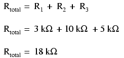
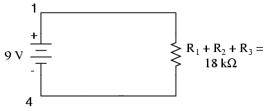
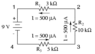
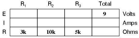
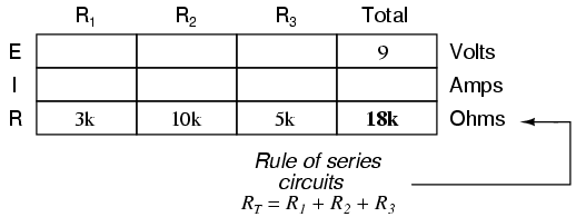
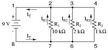
recognize a series resistor circuit
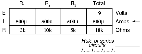
calculate the expected current in a series circuit
calculate the power dissipated in a resistor from color code
measure the voltage across a resistor or circuit
measure the current through a resistor circuit
recognize several types of switches
determine circuit paths in switched circuits
Thank you ! That was very helpful !
ReplyDelete