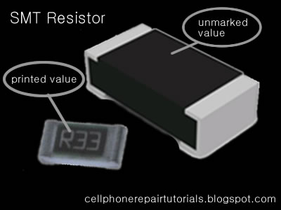
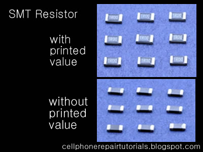
SMT Resistor ( Unprinted )
In Mobile Phones Surface Mount Molded (SMD) Resistor where not printed with numerical value and it is left blank, the problem is that it is too tiny or small to print at..You can refer only its value by an aide of Schematic Diagram Available for that certain products. Or you can Identify and check its value by using Resistance Tester...
In Schematic Diagram Its Original value where indicated: For Example:
Resistances less than 1000 ohms or 1K with ''R'' indicated in the middle indicates a decimal point like:
4R7 = 4.7Ω
2R2 = 2.2Ω
and the rest just like how it does indicated like:
100Ω = 100 ohms
220Ω = 200 ohms
and up
4.7K = 4.7 kiloohms
The Printed SMD Resistor
Zero ohm resistors Surface mounted resistors are printed with numerical values in a code related to that used on axial resistors. Standard-tolerance Surface Mount Technology (SMT) resistors are marked with a three-digit code, in which the first two digits are the first two significant digits of the value and the third digit is the power of ten (the number of zeroes). For example:
334 = 33 × 10,000 Ω = 330 kΩ
222 = 22 × 100 Ω = 2.2 kΩ
473 = 47 × 1,000 Ω = 47 kΩ
105 = 10 × 100,000 Ω = 1 MΩ
Resistances less than 100 ohms are written: 100, 220, 470. The final zero represents ten to the power zero, which is 1. For example:
100 = 10 × 1 Ω = 10 Ω
220 = 22 × 1 Ω = 22 Ω
Resistances less than 10 ohms have 'R' to indicate the position of the decimal point (radix point). For example:
4R7 = 4.7 Ω
0R22 = 0.22 Ω
0R01 = 0.01 Ω
Precision resistors are marked with a four-digit code, in which the first three digits are the significant figures and the fourth is the power of ten. For example:
1001 = 100 × 10 ohms = 1 kΩ
4992 = 499 × 100 ohms = 49.9 kΩ
1000 = 100 × 1 ohm = 100 Ω
"000" and "0000" sometimes appear as values on surface-mount zero-ohm links, since these have (approximately) zero resistance.
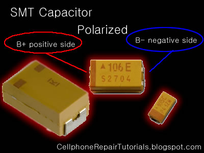
The types of capacitor which is commonly used in small space circuit like the cellphone uses the Tantalum type of capacitor,
Tantalum capacitors are used in smaller electronic devices including portable telephones, pagers, personal computers, and automotive electronics.
It also offer smaller size and lower leakage than standard. .
There are two types of Capacitors used in Mobile Phones Circuits,
The Polarized and Non-Polarized Capacitors.
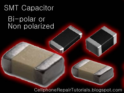
This are the Capacitors may look like that are being used in mobile phones circuit.
The Polarized Capacitor
Tantalum Capacitors which is polarized, and may be used in DC circuits. Typical values range form 0.1uF to 470uF.
Standard Tantalum values change in multiples of 10, 22, 33, and 47. Normal Temperature Coefficient [TC] for Tantalum Capacitors is +5%.
Polarized capacitors are typically used in large voltage situations, such as DC line filtering to reduce noise related to uneven voltage levels after rectification from an AC source. Mainly measured in microfarads. Polarity is critical to these devices. They are marked with the voltage rating (usually double the circuit voltage used) as well as the farad marking.
Non-Polarized Capacitor
Non-polarized are similar to polarized except the plates are similar metal.
Polarized caps are typically used in large voltage situations, such as DC line filtering to reduce noise related to uneven voltage levels after rectification from an AC source. Mainly measured in microfarads. Polarity is critical to these devices. They are marked with the voltage rating (usually double the circuit voltage used) as well as the farad marking.
non-polarized caps are typically used in low voltage situations, both AC and DC. Polarity is not critical. Measured in pico farads typically.
| Abbrev. | Prefix | Multiply by | or |
| p | pico | 0.000000000001 | 10-12 |
| n | nano | 0.000000001 | 10-9 |
| µ | micro | 0.000001 | 10-6 |
| m | milli | 0.001 | 10-3 |
| - | UNIT | 1 | 100 |
| k | kilo | 1000 | 103 |
| M | mega | 1000000 | 106 |
| Units | ||
| 1000 pico units | = | 1 nano unit |
| 1000 nano units | = | 1 micro unit |
| 1000 micro units | = | 1 milli unit |
| 1000 milli units | = | 1 unit |
| 1000 units | = | 1 kilo unit |
| 1000 kilo units | = | 1 mega unit |
Tolerance | ||
A transistor is a semiconductor device used to amplify and switch electronic signals. It is made of a solid piece of semiconductor material, with at least three terminals for connection to an external circuit.
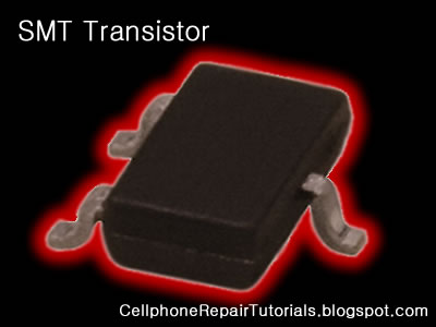
A voltage or current applied to one pair of the transistor's terminals changes the current flowing through another pair of terminals. Because the controlled (output) power can be much more than the controlling (input) power, the transistor provides amplification of a signal. Some transistors are packaged individually but many more are found embedded in integrated circuits.
The transistor is the fundamental building block of modern electronic devices, and its presence is ubiquitous in modern electronic systems.
Types of transistor
Transistor circuit symbols
There are two types of standard transistors, NPN and PNP, with different circuit symbols. The letters refer to the layers of semiconductor material used to make the transistor. Most transistors used today are NPN because this is the easiest type to make from silicon. This page is mostly about NPN transistors and if you are new to electronics it is best to start by learning how to use these first. The leads are labelled base (B), collector (C) and emitter (E).
The leads are labelled base (B), collector (C) and emitter (E).
These terms refer to the internal operation of a transistor but they are not much help in understanding how a transistor is used, so just treat them as labels!
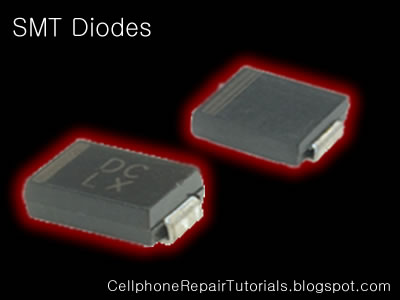
In electronics, a diode is a two-terminal electronic component that conductselectric current in only one direction. The term usually refers to a semiconductor diode, the most common type today, which is a crystal of semiconductorconnected to two electrical terminals, a P-N junction. A vacuum tube diode, now little used, is a vacuum tube with two electrodes; a plate and a cathode.
The most common function of a diode is to allow an electric current in one direction (called the diode's forward direction) while blocking current in the opposite direction (the reverse direction). Thus, the diode can be thought of as an electronic version of a check valve. This unidirectional behavior is called rectification, and is used to convert alternating current to direct current, and extract modulation from radio signals in radio receivers.
However, diodes can have more complicated behavior than this simple on-off action, due to their complex non-linear electrical characteristics, which can be tailored by varying the construction of their P-N junction. These are exploited in special purpose diodes that perform many different functions. Diodes are used to regulate voltage (Zener diodes), electronically tune radio and TV receivers (varactor diodes), generate radio frequency oscillations (tunnel diodes), and produce light (light emitting diodes).
Diodes were the first semiconductor electronic devices. The discovery of crystals'rectifying abilities was made by German physicist Ferdinand Braun in 1874. The first semiconductor diodes, called cat's whisker diodes were made of crystals of minerals such as galena. Today most diodes are made of silicon, but othersemiconductors such as germanium are sometimes used.
Types of semiconductor diode in Mobile Phones Circuit
Zener diodes
- Diodes that can be made to conduct backwards. This effect, called Zener breakdown, occurs at a precisely defined voltage, allowing the diode to be used as a precision voltage reference. In practical voltage reference circuits Zener and switching diodes are connected in series and opposite directions to balance the temperature coefficient to near zero. Some devices labeled as high-voltage Zener diodes are actually avalanche diodes (see above). Two (equivalent) Zeners in series and in reverse order, in the same package, constitute a transient absorber (or Transorb, a registered trademark). The Zener diode is named for Dr. Clarence Melvin Zener of Southern Illinois University, inventor of the device.
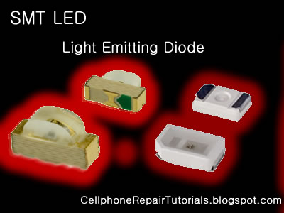
- In a diode formed from a direct band-gap semiconductor, such as gallium arsenide, carriers that cross the junction emit photons when they recombine with the majority carrier on the other side. Depending on the material, wavelengths (or colors) from the infrared to the near ultraviolet may be produced. The forward potential of these diodes depends on the wavelength of the emitted photons: 1.2 V corresponds to red, 2.4 V to violet. The first LEDs were red and yellow, and higher-frequency diodes have been developed over time. All LEDs produce incoherent, narrow-spectrum light; “white” LEDs are actually combinations of three LEDs of a different color, or a blue LED with a yellow scintillator coating. LEDs can also be used as low-efficiency photodiodes in signal applications. An LED may be paired with a photodiode or phototransistor in the same package, to form an opto-isolator.
- Photodiodes
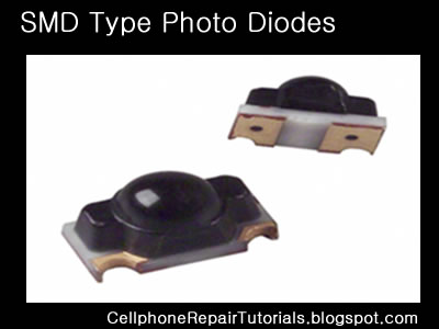
- All semiconductors are subject to optical charge carrier generation. This is typically an undesired effect, so most semiconductors are packaged in light blocking material. Photodiodes are intended to sense light(photodetector), so they are packaged in materials that allow light to pass, and are usually PIN (the kind of diode most sensitive to light). A photodiode can be used insolar cells, in photometry, or in optical communications. Multiple photodiodes may be packaged in a single device, either as a linear array or as a two-dimensional array. These arrays should not be confused withcharge-coupled devices.
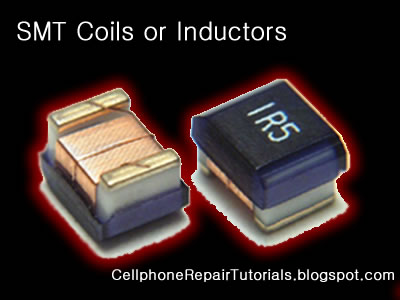
An inductor or a reactor is a passive electrical component that can store energy in a magnetic field created by the electric current passing through it. An inductor's ability to store magnetic energy is measured by its inductance, in units ofhenries. Typically an inductor is a conducting wire shaped as a coil, the loops helping to create a strong magnetic field inside the coil due to Faraday's Law of Induction. Inductors are one of the basic electronic components used in electronics where current and voltage change with time, due to the ability of inductors to delay and reshape alternating currents.
Inductance (L) (measured in henries) is an effect resulting from the magnetic fieldthat forms around a current-carrying conductor which tends to resist changes in the current. Electric current through the conductor creates a magnetic fluxproportional to the current, and a change in this current creates a corresponding change in magnetic flux which, in turn, by Faraday's Law generates anelectromotive force (EMF) that opposes this change in current. Inductance is a measure of the amount of EMF generated per unit change in current. For example, an inductor with an inductance of 1 henry produces an EMF of 1 volt when the current through the inductor changes at the rate of 1 ampere per second. The number of loops, the size of each loop, and the material it is wrapped around all affect the inductance. For example, the magnetic flux linking these turns can be increased by coiling the conductor around a material with a high permeability such as iron. This can increase the inductance by 2000 times, although less so at high frequencies.
Inductors are used extensively in analog circuits and signal processing. Inductors in conjunction with capacitors and other components form tuned circuits which can emphasize or filter out specific signal frequencies. Applications range from the use of large inductors in power supplies, which in conjunction with filter capacitorsremove residual hums known as the Mains hum or other fluctuations from the direct current output, to the small inductance of the ferrite bead or torus installed around a cable to prevent radio frequency interference from being transmitted down the wire. Smaller inductor/capacitor combinations provide tuned circuits used in radio reception and broadcasting, for instance.
An electronic oscillator is an electronic circuit that produces a repetitive electronic signal, often a sine wave or a square wave.
A low-frequency oscillator (LFO) is an electronic oscillator that generates an AC waveform at a frequency below ≈20 Hz. This term is typically used in the field of audio synthesizers, to distinguish it from an audio frequency oscillator.
Oscillators designed to produce a high-power AC output from a DC supply are usually called inverters.
The waveform generators which are used to generate pure sinusoidal waveforms of fixed amplitude and frequency are called oscillators.
Crystal oscillator
A crystal oscillator is an electronic circuit that uses the mechanical resonance of a vibrating crystal of piezoelectric material to create an electrical signal with a very precise frequency. This frequency is commonly used to keep track of time (as in quartz wristwatches), to provide a stable clock signal for digital integrated circuits, and to stabilize frequencies for radio transmitters and receivers. The most common type of piezoelectric resonator used is the quartz crystal, so oscillator circuits designed around them were called "crystal oscillators".
Quartz crystals are manufactured for frequencies from a few tens of kilohertz to tens of megahertz. More than two billion (2×10⁹) crystals are manufactured annually. Most are small devices for consumer devices such as wristwatches, clocks, radios, computers, and cellphones. Quartz crystals are also found inside test and measurement equipment, such as counters, signal generators, and oscilloscopes.
Voltage-controlled oscillator
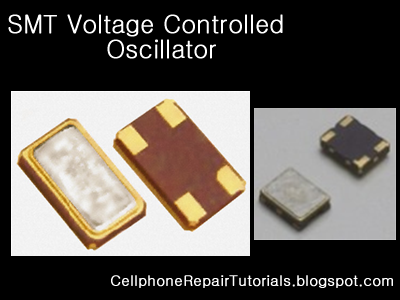
A voltage-controlled oscillator or VCO is an electronic oscillator designed to be controlled in oscillation frequency by a voltage input.
The frequency of oscillation is varied by the applied DC voltage, while modulating signals may also be fed into the VCO to cause frequency modulation (FM) or phase modulation (PM); a VCO with digital pulse output may similarly have its repetition rate (FSK, PSK) or pulse width modulated (PWM).
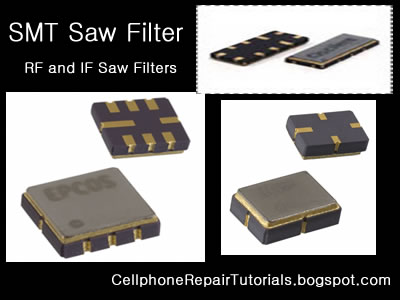
Electronic filters are electronic circuits which perform signal processing functions, specifically to remove unwanted frequency components from the signal, to enhance wanted ones, or both. Electronic filters can be:
Radio frequency (RF) and microwave filters represent a class of electronic filter, designed to operate on signals in the megahertz to gigahertz frequency ranges (medium frequency to extremely high frequency). This frequency range is the range used by most broadcast radio, television, wireless communication (cellphones, Wi-Fi, etc...), and thus most rf and microwave devices will include some kind of filtering on the signals transmitted or received.
Radio frequency (RF) and microwave filters represent a class of electronic filter, designed to operate on signals in the megahertz to gigahertz frequency ranges (medium frequency to extremely high frequency). This frequency range is the range used by most broadcast radio, television, wireless communication (cellphones, Wi-Fi, etc...), and thus most rf and microwave devices will include some kind of filtering on the signals transmitted or received.
Such filters are commonly used as building blocks for duplexers and diplexers to combine or separate multiple frequency bands.
Electrostatic discharge (ESD) is the sudden and momentary electric current that flows between two objects at different electrical potentials caused by direct contact or induced by an electrostatic field. The term is usually used in the electronics and other industries to describe momentary unwanted currents that may cause damage to electronic equipment.
ESD is a serious issue in solid state electronics, such as integrated circuits. Integrated circuits are made from semiconductor materials such as silicon and insulating materials such as silicon dioxide. Either of these materials can suffer permanent damage when subjected to high voltages; as a result there are now a number of antistatic devices that help prevent static build up.
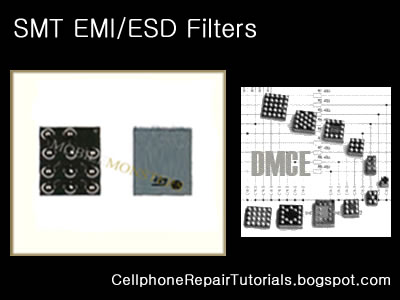
Below are common types of EMI-ESD protection chips used among various mobile phone's circuit.
Electromagnetic interference (or EMI, also called radio frequency interference or RFI) is a disturbance that affects an electrical circuit due to either electromagnetic conduction or electromagnetic radiation emitted from an external source. The disturbance may interrupt, obstruct, or otherwise degrade or limit the effective performance of the circuit. The source may be any object, artificial or natural, that carries rapidly changing electrical currents, such as an electrical circuit, the Sun or the Northern Lights.
EMI can be intentionally used for radio jamming, as in some forms of electronic warfare, or can occur unintentionally, as a result of spurious emissions for example through intermodulation products, and the like. It frequently affects the reception of AM radio in urban areas. It can also affect cell phone, FM radio and television reception, although to a lesser extent.




Very very good post. It is very useful for someone. I mostly request u to post many more like this. Please Please Please...........
ReplyDeleteThis is my mail address, give me some advice, i am very interested in invention of new thing. Help me...........
ReplyDeleteshiponnn4@gmail.com
ReplyDeleteVery useful to us doing projects 1
ReplyDeleteThank you!!!!
ReplyDeletethenks thenks bohat achi tips
ReplyDeletethanks great work
ReplyDeleteVery useful and informative!
ReplyDeleteHow can check 220 pf and 2.2 pf smd capacitor they have same colour
ReplyDeleteThank very much, this is very useful
ReplyDeleteThanks sir
ReplyDeleteCapture the colours of the world in their truest form with the revolutionary Find X3 Pro. Rich tones and deep hues combine to illuminate the road to the future. This is one of the best Android Phones.
ReplyDeleteFind X3 Pro 5G